|
INSTRUCTIONS FOR OPERATING GORTER
WATER TOWER
A. Check the Following Items:
- Close mast drain valve. (underneath mast)
- Close the Tower and Turret supply valves.
- Close the pressure release valve (dump valve) by moving lever inward.
- Turn water motor control valve to S (stop).
- Disengage all dog clutches.
- See that extension power shaft universal joint is in proper alignment
(by use of
arrow and indicator on small gear).
- See that power shaft friction clamp is locked.
THE APPARATUS SHOULD BE MAINTAINED IN THE ABOVE CONDITION IN QUARTERS AND BE READY FOR
IMMEDIATE RESPONSE.
B. Place Into Position:
- Spot tower as ordered, watch overhead wires and other obstructions.
- Place chock blocks under rear wheels, left front and right rear.
Note: Use wheel plate under rear wheel on side away from fire when operating on soft
ground or pavement. On a hill or soft ground use large wheel chock block in addition to
other chock blocks. If plate is used place chocks fore and aft on wheel on the fire side.
- Set spring jacks, use wood plates.
Adjust until firm, but do not take weight on jacks.
- Place both struts out, secure chains to struts and wheel spokes and adjust.
- Connect hose lines to intake manifold.
(use shut-off butts unless water supply is from a manifold wagon or cluster of a dual
carrier.
C. Raise Mast (about 90 lbs pressure)
- Engage dog clutch on left side of water motor.
- Open water motor control to R, raise mast.
- When mast reaches vertical position where vertical brace is mid-way between arrows, turn
control valve to S, stop.
- Line up ball joint, make sleeve connection at base of mast. (use tool, (pipe) to
tighten)
- Disengage left side dog clutch.
|
|
D. Raise Extension
- Engage dog clutch on right side of water motor.
- Release friction lock on extension drive shaft.
- Use lever on mast to engage extension gears.
(use ratchet on drive shaft to mesh if necessary)
- Turn water motor control valve to Raise, and raise to desired height
(white lines are limit warning)
- Turn motor control valve to S, stop, disengage dog clutch.
- Lock extension drive shaft friction lock.
- Direct nozzle by controls at base of tower.
Rear handle - Vertical control
Front handles - Horizontal control
Open water tower supply valve

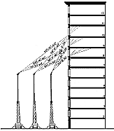
WATER
STREAM ANGLES
SHUTTING DOWN OPERATIONS
E. Lower Extension
- Open tower drain valve.
- Release extension drive shaft friction lock.
- Engage right dog clutch.
- Open water motor control to L, lower extension.
Ease extension onto seat, (pressure release valve, dump valve, may be used to slow
speed as extension nears down position.)
- Disengage right dog clutch.
- Disengage extension gear lever on mast, use ratchet when necessary.
Put ratchet lever in neutral after use.
|
|
F. Lower Mast
- Line up extension universal joint using arrow and indicator on small gear.
- Lock extension drive shaft lock.
- Disconnect ball joint connection at base of mast.
- Engage left dog clutch.
- Open water motor control to L, lower.
- Ease mast onto supports and return water motor control to S.
- Disengage left side dog clutch.
G. Pick Up
- Drain system.
- Release, pick up, and replace, spring jacks, struts, chains,
chock blocks, and other equipment.
- Check all items listed in Section A
H. Lubrication after Use
- Few drops engine oil at all oil points.
- Refill grease cups.
- Drain water from worm gear oil pans, (pet cocks underneath)
Refill oil pans.
I. General Information
- Operating pressure is about 90 to 120 pounds pressure.
- Horizontal sweep of Tower Nozzle is 270 degrees.
(Blind 90 degrees directly to the rear)
- Height of Nozzle from street.
Mast not extended- 37 feet
Extended- 55 feet
- Tip sizes for Tower Nozzle
1 1/2"
1 3/4"
2"
- Tip sizes for Turret Nozzle
1 1/2" - 600 gpm
1 3/4" - 800 gpm
2" - 1000 gpm
2 1/4" - 1350 gpm
(Tips are not interchangeable)
Nozzle pressure about 80 pounds.
FOR QUESTIONS-
CONTACT APPARATUS OPERATOR MICHAEL BREHM,
FIRE STATION 12,
"C" PLATOON
213 485-6212
|
